


Due to the flaw detector is designed in a form of a standalone device with the connection to the PC via Ethernet port, the several UT channels can be connected to the PC via Switch unit. This allows to create UT multi-channel testing systems.
Technical capabilities of the flaw detector allow to use it both in stationary-type in-line and off-line testing systems.
APPLICATION OF ULTRASONIC TESTING TECHNIQUE IN VARIOUS INDUSTRIES:
| Production sector, test object | Regulatory Documentation | Required number of channels | Operating frequency, MHz | Testing techniques |
| Metallurgy, testing the flat rolled steel | EN10160, ASTM 578/A578M-96, A435A, ISO 12094 | 60-100 | 2-5 | Immersion or contact |
| Metallurgy, testing the rolled round steel bars | EN 10308, EN 10228-3, ASTM E – 2375, MS-STD – 2154 | 3-20 | 2-10 | Immersion or contact, testing velocity is up to 2 m/s |
| Engineering, testing the pipe welded joints | API 5L, API5 CT, EN 10246-17 | 12 | 2-5 | Immersion or contact, velocity is up to 2 m/s |
| Engineering, testing the pipe body, thickness gauging | API 5L, API5CT, EN 10246, ASTM E1816-96 | 56 | 2-5 | Immersion or contact, velocity is up to 1 m/s. Resonance-frequency technique for measuring the pipe wall thickness – from 0.2 to 5.0 mm. |

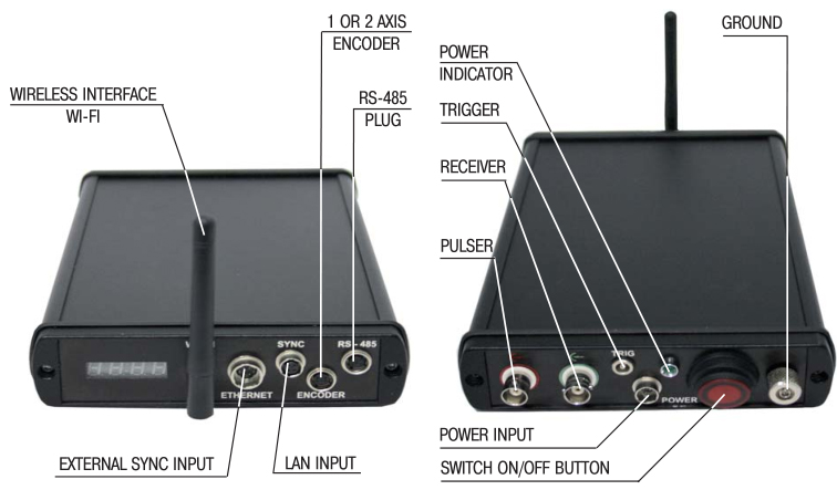
Figure 1 – UT channel "ОКО-22М"
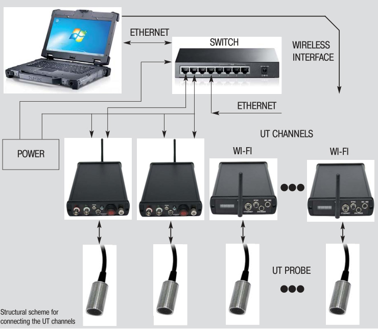
Figure 2 - Structural scheme for connecting the UT channels

THE ОКО-22М-UT MAIN SPECIFICATIONS
| Parameter | OKO-22M-UT Standart | OKO-22M-UT StandartMX | OKO-22M-UT PRO |
| Pulser | |||
| Pulse mode | Spike pulser | Spike pulser, Square-wave pulser | |
| Pulse Voltage (SQ mode) | 120-300 V in steps 10 V with tolerance 10% | ||
| Pulse falling/rising time | 5 ns | ||
| Pulse Width (SQ mode) | 20 – 500 ns in steps 10 ns with tolerance 10% | ||
| PRF (SQ mode) |
15 – 2000 Hz in steps 5 Hz, 3 automatic modes: Auto Low, Auto Med, Auto High, Manual |
||
| Pulse Voltage (spike mode) | Low (100 V), High (400 V) | ||
| Pulse energy (spike mode) | Low (30 ns), High (100 ns) | ||
| PRF (spike mode) |
15 – 100000 Hz in steps 5 Hz, 3 automatic adjustment modes: Auto Low, Auto Med, Auto High, Manual |
||
| Damping | 50, 62, 150, 400 | ||
| Receiver | |||
| Gain | 0 to 110 dB adjustable in steps of 0.2, 0.5, 1, 2 dB | ||
| Receiver input impedance | 400Ω±5% | ||
| Receiver bandwidth | 0.2-27 MHz (- 3 dB) | ||
| Digital filter setting | Eight digital filter sets standard (0.2-10 MHz; 2.0-21.5 MHz; 8.0-26.5 MHz; 0.5-4 MHz; 5-15 MHz; 5-15 MHz; DC-10 MHz) |
||
| Rectification | Fullwave, positive halfwave, negative halfwave, RF | ||
| Amplitude measurement | 0-110% | ||
| Reject | 0-80% FSH | ||
| Units | Millimeters, inch or microseconds | ||
| Range | 1 to 6000 mm | ||
| Velocity range | 1000 to 10000 m/s in steps of 1, 10, 100, 1000 m/s | ||
| Thickness measurements range | 0.6 to 6000 mm | ||
| Probe angle | 0°to 90°in steps 0.1°, 1.0°, 10° | ||
| Digital cpecification | |||
| ADC | 10 – bits with the sampling rate 100 MHz | ||
| A-Scan buffer | Raw data | 8 KB | |
| Gate | |||
| Measurements gates |
|
||
| Start Gate | Variable over entire range | ||
| Width Gate | Variable over entire range | ||
| Gate height | Variable from 2 to 100% FSH | ||
| Measurement specification | |||
| Result display | A-scan, B-scan, C-scan, D-scan | ||
| DAC/TCG |
|
||
|
DGS |
|
||
| Connectors | |||
| Number channels | 1 | up to 8 | 1 |
| Probe connector | 2 BNC or 2 Lemo 1S | BNC | 2 BNC or 2 Lemo 1S |
| USB port | USB-2.0 | ||
| Ethernet | + | ||
| WI-FI | antenna plug in | ||